


10 Common Plastic Injection Mould Design Mistakes and How to Avoid Them

Most design flaws start long before the first part is molded. They cause costly production delays, part defects and high scrap rates. Small mistakes made early multiply into major, expensive problems.
Proper planning at the earliest stage prevents costly tool rework and material waste. Many issues are completely avoidable with basic care and review. The right plastic injection mould design addresses all of these risks before tooling.
10 Common Plastic Injection Mould Design Mistakes
1. Inconsistent Wall Thickness
The thick sections adjacent to thin ones cause uneven cooling across the part. Heavier areas shrink at a far higher rate than thin areas of the part. Sink marks form on the surface opposite thick internal ribs and bosses. Internal voids develop deep inside the thickest sections of the finished part.
The good plastic injection mold design keeps the wall thickness between 1mm and 4mm. Maintain a maximum thickness ratio of 3:1 between any adjacent sections.
Core out thick areas to remove excess mass without losing structural strength. Use ribbing instead of thickening entire sections of the part to add strength.
2. Incorrect Gate Sizing
The gates that are too small freeze off before the cavity fills. The oversized gates create excessive residual stress at the gate location on the part.
The gate freeze time is longer than the cooling time. This wastes valuable cycle time every shot. Poor gate selection causes visible flow lines and weak weld lines across the part.
A good plastic mold design company will validate all gate choices before cutting tooling. Always position gates at the thickest section of the part inside the mold cavity.
Avoid placing gates on long and thin parts of walls. Locate gates away from all visible class A cosmetic surfaces of the finished part. Use multiple gates for large or unusually long part geometries.
|
Gate Size and Location Guidelines |
|||
|
Wall Thickness |
Recommended Gate Size |
Gate Type Options |
Maximum Gate Distance |
|
1.0 mm |
0.5 - 0.7 mm |
Pin point, submarine |
75 mm |
|
1.5 mm |
0.8 - 1.0 mm |
Edge, tab, submarine |
100 mm |
|
2.0 mm |
1.0 - 1.4 mm |
Edge, fan, tab |
125 mm |
|
2.5 mm |
1.3 - 1.8 mm |
Edge, fan, sprue |
150 mm |
|
3.0 mm |
1.5 - 2.1 mm |
Edge, fan, diaphragm |
175 mm |
|
4.0 mm |
2.0 - 2.8 mm |
Fan, sprue, direct |
200 mm |
2. Missing Draft Angles
The zero draft on vertical walls causes parts to stick firmly inside the mold cavity. The parts will scrape and scuff during ejection if the draft is insufficient for the resin.
The high ejection forces will break small part features during demolding. Surface finish degrades from friction against the hardened steel cavity. Mold cavity walls wear much faster when no draft is applied to vertical surfaces.
The custom plastic injection part design will have a minimum 1-2 degrees draft on all vertical part walls. Add one additional degree per inch of total cavity depth inside the mold. Textured surfaces require one degree per 0.001 inch of texture depth applied.
4. Ignoring Undercut Geometry
The internal and external undercuts prevent straight line opening of the mold. Parts will lock permanently into the cavity if undercuts are left unaddressed. Manual side actions add significant time to every single production cycle.
The plastic injection mould design eliminates undercuts. Use bump-offs for very small undercuts between 0.005 and 0.010 inches. Plan for side cores or lifters early in the initial mold layout stage.
Use collapsible cores for all internal threads and ring features on the part. Unscrewing devices provide the best solution for external thread features.
5. Poor Cooling Line Layout
The uneven cooling creates consistent hot spots across the mold cavity. Inefficient heat removal leads to unnecessarily long cooling times per cycle. Temperature variations across the mold cause consistent dimensional inconsistency. Thick sections remain hot while thin sections cool long before them.
Space cooling channels 2-3 times their diameter apart from each other. A competent plastic mold design company will keep channels 1.5-2 times their diameter from the surface of the cavity. Use a minimum channel diameter of 10-12mm for all full production tools.
Follow the part contour exactly with conformal cooling. Cool the core and cavity halves of the mold separately from each other. The baffles and bubblers provide cooling for hard-to-reach internal areas of the mold.
6. Trapped Air Pockets
Air trapped inside the cavity causes incomplete fill and short shots. The thin ribs and bosses will often remain unfilled due to trapped air. The diesel effect creates small black spots on the surface of the part. Trapped air builds pressure that prevents a complete cavity fill at full pressure.
Place vents at the parting line at all last fill locations inside the mold. Vent depth should be between 0.0005 and 0.002 inches for most resins. Standard vent width falls between 0.125 and 0.250 inches for most tools. Add additional vents at the end of every long material flow path.
7. Sharp Corners
Sharp internal corners create extreme stress concentrations in finished parts. Material flow hesitates significantly at all 90-degree internal corners. Weld lines form after flow separates around sharp corners. Air becomes trapped at the intersection of two sharp internal corners.
Add a minimum 0.5mm radius to every internal corner of the part. Use a radius equal to 25-40% of the nominal part wall thickness. Fillet all external corners to remove sharp and dangerous exposed edges. The rounded corners improve the flow characteristics of all common resins.
8. Ejector Pin Marks
The ejector pins placed on class A surfaces create permanent cosmetic defects. Small-diameter pins create high local pressure during part ejection. Insufficient total pin area leads to permanent deformation of the part.
Always place ejector pins on non cosmetic surfaces. Use the largest possible diameter pins to spread the ejection force evenly.
Add small ejector pin pads to thin walls to prevent deformation. Use sleeve ejectors for all cylindrical and tubular part features. Maintain maximum ejection pressure below 5 psi across the entire part.
9. Texture Depth
The heavy textures applied without additional draft will stick inside the mold. Deep grain patterns increase the required ejection force. The texture applied against the draw direction causes permanent drag marks.
The mismatched polish and texture create an inconsistent finish across the part. Unspecified SPI finish standards lead to unexpected finish results.
Add 1-1.5 degrees additional draft per 0.001 inch of texture depth. Always apply all textures exactly parallel to the draw direction of the part. Specify exact SPI finish standards for every surface of the part. Use EDM textures for a consistent finish on complex part geometries.
10. Tight Tolerances
Specifying tolerances tighter than material capability is a common mistake. Different resins have different and consistent shrinkage characteristics.
Always check the published shrinkage rate for the selected resin in the custom plastic injection part design. Apply the correct shrinkage factor to all dimensions of the mold. Glass-filled materials shrink less but vary significantly by direction.
Allow 0.003 inch per inch tolerance for semi-crystalline materials. Allow 0.002 inch per inch tolerance for all amorphous materials. Always prototype and test parts before finalising production tooling.
How Plastic Injection Molding Helps Avoid These Design Mistakes?
Plastic Injection Molding is the leading supplier of custom injection molded plastic parts for all industry sectors. Their engineers identify wall thickness issues early in the process. The teams optimize gate location and size for every individual part. They calculate and apply the correct draft angle for every feature.
Cooling line layout receives full optimisation for every production tool. The engineers develop a complete venting strategy for the entire cavity. They provide recommendations for corner radius and ejection layout.
The engineers complete a full tolerance stack-up analysis for all dimensions. Mold flow simulation accurately predicts defects before tooling. The first article inspection validates all dimensions and part characteristics.
Material shrinkage testing confirms all assumptions made during design. Process parameters are developed and locked before full production. This process prevents almost all costly and time-consuming mold revisions. This process delivers consistent, high-quality custom injection molded plastic parts at volume.
Additional final considerations:
● All design reviews are completed by senior tooling engineers
● No design change proceeds without formal written approval
● Full simulation reports are provided with every design package
● Ongoing support is provided for the full life of the tool
Conclusion
Design mistakes do not stay small once production gets underway. They multiply rapidly into expensive and disruptive production nightmares. Wall thickness, draft, cooling and venting are all equally critical. The rigorous review of plastic injection mold design stops most issues. Most common mistakes are easy to avoid.
A professional independent mold design review catches errors early. It is cheaper to fix a design on a computer screen. Fixing the same mistake once steel has been cut costs ten times more.
Small design mistakes can add huge costs, delays and part defects later. If you would like an experienced engineer to review your current design for these common mistakes, call us at +1 917-730-4350 or send your files to info@plastic-injectionmolding.com. We will give you practical feedback and tell you exactly what changes will save you time and money on your project.
Nach Verein filtern
Read More
GV Gallery Clothing – Where Streetwear Meets Art and Attitude GV Gallery Clothing is one of the fastest-rising names redefining the boundaries of modern streetwear. Known for its bold aesthetic, high-end quality, and creative storytelling, GV Gallery stands as a symbol of individuality and culture. The brand merges urban fashion with artistic expression, delivering clothing that...

Outdoor Driveway Lighting is more than a decorative addition to your property. A well-planned lighting system improves visibility, enhances security, and creates a welcoming atmosphere for family members and visitors. Whether you have a modern home or a traditional property, the right lighting design can significantly increase both functionality and curb appeal. One of the biggest...

Buy Tyres Online in Kuwait: A Smart and Convenient Way to Upgrade Your Vehicle Choosing to buy tyres online in Kuwait has become one of the most convenient ways for drivers to upgrade their vehicles without hassle. With Kuwait’s roads demanding high-performance, durable, and safe tyres, car owners are shifting from traditional tyre shops to trusted online platforms. Buying tyres online...
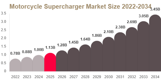
Motorcycle Supercharger Market Overview The Motorcycle Supercharger Market is witnessing steady growth driven by increasing demand for high-performance motorcycles, rising motorsport participation, and growing consumer preference for premium biking experiences. Motorcycle superchargers are forced induction systems designed to increase engine power by compressing intake air, improving combustion...
According to the latest report published by Data Bridge Market Research, the Surgical Incision Closure Market The global surgical incision closure market was valued at USD 15.97 billion in 2025 and is projected to reach USD 29.34 billion by 2033, growing at a CAGR of 7.90% from 2026 to 2033. This Surgical Incision Closure Market document encompasses several market aspects...
